Basic Considerations About Air Cycle Cooling Systems (ACCS)
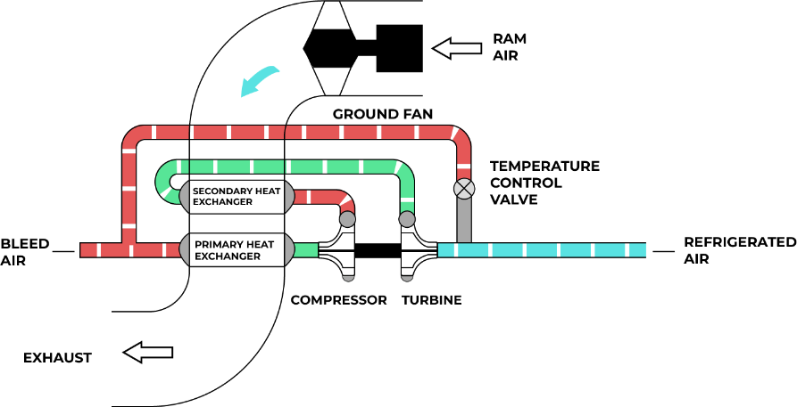
- Basically, the air cycle cooling system is supplied from air bled from the main engine compressor. The air is expanded through an air turbine that drives a compressor or fan, thus converting heat energy into useful work.
- For low speed flight, integrated cooling and pressurization requirements for cabin cooling can be met advantageously by air cycle systems. As a result, most propeller driven and many jet transports use air cycle systems for cooling and pressurization.
- During high speed flight at high altitudes, maximum cooling requirements are coincident with maximum pressurization requirements.
- For any application involving a high heat load, the amount of air flow required for cooling is considerable, requiring large diameter ducts and a large ram air drag penalty. If bleed air from a jet engine is used, the high mass flow necessary would result in high fuel penalties. For these reasons the air cycle system has its limitations.
- Another limitation of the air cycle system is that frosting in the downstream air ducts can occur if the turbine outlet temperature falls to the freezing point.
Basic Air Cycle
Thermodynamic Evaluation of Air Vehicle Air Cycle Cooling Systems (ACCS)
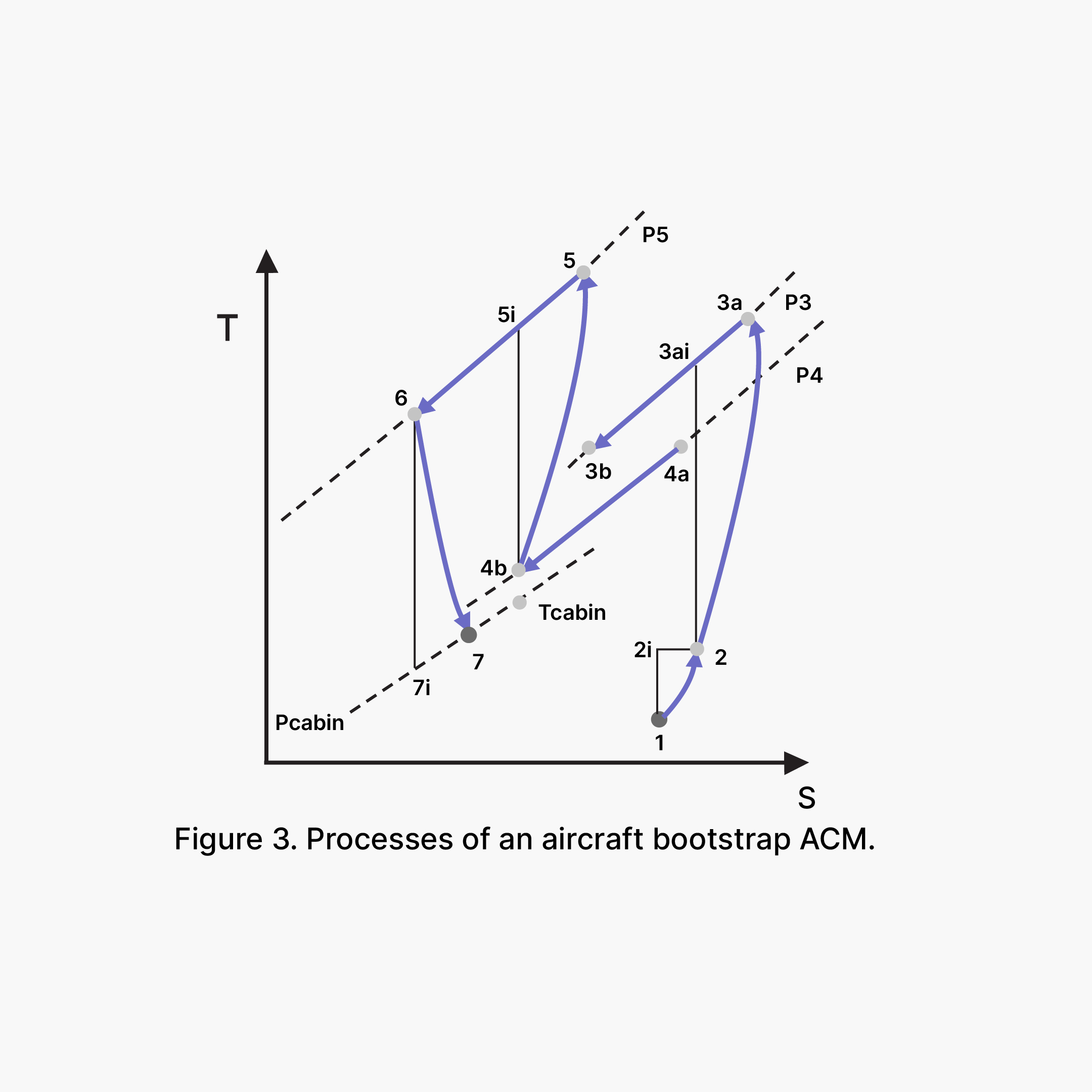
A typical open bootstrap air cycle machine processes (1-7) can be plotted in a temperature vs entropy diagram, as schematized in Figure 3
where:
- 1 ambient static conditions;
- 2 state after ram air compression;
- 3a propulsion turbine compressor (primary compressor) exit;
- 3b bleed pre-cooler (heat exchanger) exit;
- 4a bleed pressure control valve exit;
- 4b ACM primary heat exchanger exit;
- 5 ACM compressor (secondary compressor) exit;
- 6 ACM secondary heat exchanger exit;
- 7 ACM turbine exit;
- i isentropic process exit;
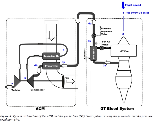
- When the aircraft is flying, the initial compression of the ambient air is due to ram effect. The ram effect is shown by line 1-2. Point 1 represents the static temperature and pressure of external ambient air, while point 2i denotes the state after isentropic compression to pressure P2i and temperature T2i- The initial compressed air required to drive the ACM is bleed of the aircraft engine, as shown in Figure 4. This first compression occurs at the propulsion turbine compressor, process 2-3a.
- The aircraft bleed system initially controls the temperature and pressure of the compressed air as shown in Figure 4. The state of compressed air supplied to the air cycle machine is represented by point 4a in T vs s diagram shown in Figure 3 and also in Figure 4 (primary heat exchanger entry). The temperature drop in the pneumatic system pre-cooler (3a-3b) does not represent a performance penalty but the pressure reduction through the pneumatic pressure control valve (3b-4a) causes a lost in the cooling effect.
- In the process 4a-4b the working fluid (air) is cooled by the ACM primary heat exchanger. Pressure P4a is equal to P4b if the fluid friction process is neglected.
- Temperature after the cooling process 4a-4b must be higher than the stagnation temperature T2 of the ambient air. It implies that the working fluid cannot be cooled by heat exchange to a temperature bellow T2.
- In the process 5-6 the working fluid (air) is cooled by the ACM secondary heat exchanger. If the fluid friction process is neglected, pressure P5 is equal to P6.
- The largest temperature drop occurs when the air expands in the turbine (expander) of the air cycle machine. (see Figure 4). In the isentropic process the state at the end of expansion process is represented by point 7i in T vs s diagram (Figure 3). For the actual conditions, the pressure P7i = P7 is slightly above the pressure of aircraft pressurized cabin (Pcabin) that is higher than the external ambient pressure. So, in the present work, it is assumed that P7 = Pcabin, neglecting the pressure drop in the air distribution ducts.