Basic Considerations About Vapor Cycle Cooling Systems (VCCS)


The vapor cycle refrigeration system is, in effect, a heat pump, since it transfers heat from a low temperature environment to one at a higher temperature. Evaporation of the liquid refrigerant in the evaporator absorbs heat from the heat source fluid. The refrigerant is in tum compressed to a higher pressure and temperature and then cooled in a condenser where the acquired heat is rejected to the heat sink. The refrigerant liquid leaving the condenser flows to the evaporator through a throttling (expansion) valve. The vapor cycle system is a closed-circuit system.
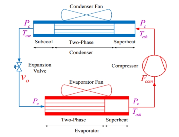
Typically, the VCC system is composed of a condenser, an evaporator, an expansion valve, and a compressor, shown in right left side.

Description of the Vapor Cycle Cooling System


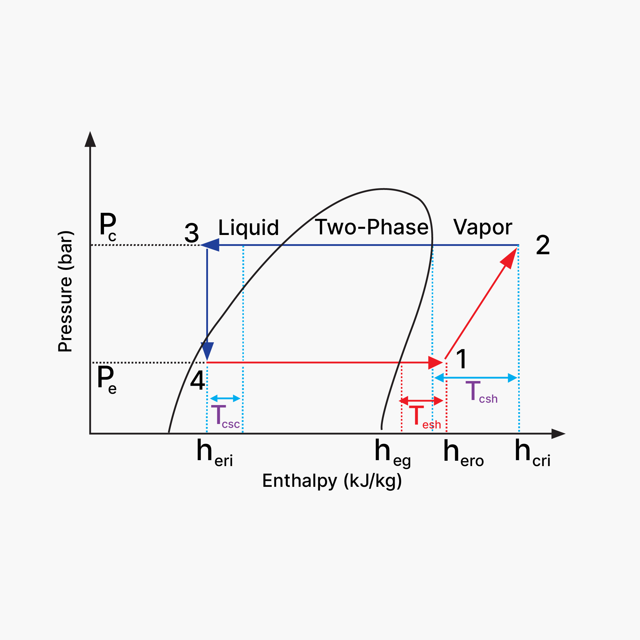
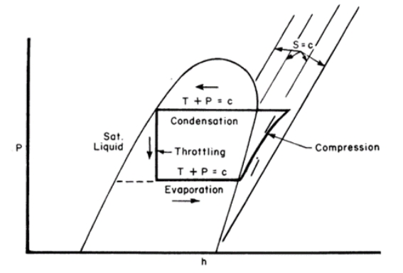
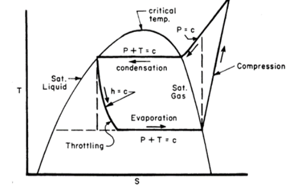
The pressure-enthalpy and temperature-entrophy diagramare illustrated on left, to describe the states of the refrigerant along cycle in the system.
The refrigerant, in state 1 with low temperature and pressure, is compressed isentropically by the compressor to increase the temperature and pressure to reach the state 2; the compressed refrigerant vapor enters into the condenser and is condensed in isobaric process to liquid phase (state 3) by transferring the heat from the refrigerant to the secondary fluid with lower temperature; the subcooled refrigerant will be expanded in isenthalpic process by the expansion valve to obtain a sudden pressure decrease and partially evaporate to lower the saturated temperature.
Thus, after the expansion valve, the refrigerant is in mixed state (liquid and gas) with low temperature and pressure (state 4). The mixed refrigerant enters into the evaporator where cooling energy is supplied by absorbing the energy from the ambient air. The cooling air is then supplied to the occupied space to meet the cooling demand. After the evaporator, the refrigerant in superheat state is drawn by the compressor to complete the refrigeration cycle.